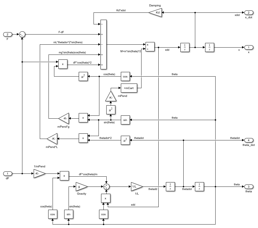
The distribution of forces of the system is shown in Figure 2.
#INVERTED PENDULUM CONTROL MATLAB SIMULINK FREE#
Figure 1 shows the free body diagram of the system. The final assumption is that an impulse input is applied to the system in order to displaceįor the analysis of the system dynamics equation, Newton’s second law (force= mass * acceleration) was utilised. The third assumption is that the pendulums brought and the hinge whether pendulums fixed has noįriction. The second assumption is that the pendulumĭoes not move away from the vertical no more than a few degrees in order to satisfy a linear model.

Initial conditions have assumed to be equal to zero. The first assumption is that the system starts at an equilibrium state and that the In order to obtain the dynamics of the system assumptions about how the system perform haveīeen determined. Rod mounted onto a cart, which can freely move in the X direction as shown in Figure 1.įigure 1: Pendulum is constrained to move in the vertical plane The modelling of the inverted pendant is shown in the section. To find the two linearised equations of motion for both the cart and the pendulum a description on The HiTechnic Angle Sensor for the EV3 was used for this project and it determines the displacement of a object in relation to the desired reference position, which in this case is the absolute angle of the pendulum and is placed on its axis of rotation. Also the mass of the rod was taken into consideration, as when you decrease the mass, the chance of it staying in equilibrium will be much

Another focus in our design was on the pendulum length, because as mentioned above, as the length the increases the centre of mass will change accordingly, making it easier for the pendulum to move back and forth. The length of the rod has a direct effect on the motion of the whole design, because the centre of mass changes with the length of the rod, thus resulting in the change of the dynamics of our desired mechanical design.Ī focus was placing the pendulum precisely in the middle of the cart in order to focus the centre of mass in the middle of the design to aid in reaching equilibrium. The total length of the rod was measured to be about 35.6 cm, however, when getting to the resolving of equations, only half the length of the rod will be used, which is about 17.8 cm. The total mass of our final design was found to be about 770 grams, including all components added, wires, wheels, etc. For the pendulum to keep in the upright position, a pendulum head was attached to the top of the rod to try to control it and prevent it from moving back and forth, thus resulting in equilibrium. The design shown below is based on the LEGO-Mindstorm EV3, and is a simple cart with two driving wheels, two fixed wheels at the bottom of it, and a pendulum attached to the top part of the cart in order to stabilise the system and help it reach equilibrium. Inverted pendulum efficiently and effectively the PID control strategy is used.

The inverted pendulum system is unstable, complicated and non-linear. Control of an inverted pendulum using PID.


 0 kommentar(er)
